The inventor
OK, it's time to continue the what-I-did-with-my-free-time-and-money-before-going-back-to-school series.
Who doesn’t want to on their own business? Since I had the know-how and certain connections with local machine shops I thought I’d design and sell retrofit kits for Razor scooters. The first few picture below are of the first prototype I made using a small 18cc engine from a leaf blower. The pictures at the bottom are CAD models of the electric version I made. I actually made the electric version, but I don’t have any photographs to post.
After looking into liability issues I realized it as going to take a lot more money, time and research to make this venture work. I was due to start law school in a few months so I abandoned the idea. Now the market is flooded with powered scooters and prices have dropped dramatically. C’est la vie.
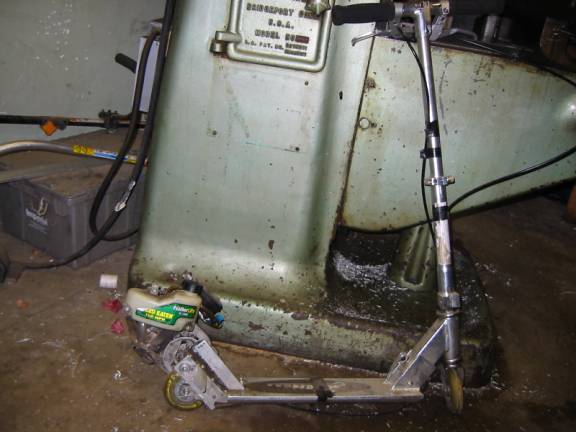
 Shown here leaning up against my milling machine on which I made all the parts for this scooter.In the background you can see some of the trimmers I was going to cannibalize for parts. I got a good deal on "remanufactured" trimmers from Harbor Freight, though it turns out all the engines were brand new.
 A better view of the power unit. The engine is mounted on a pivoting bracket. At the bottom you can see one of a pair of springs. The pivot point is that pin right above the spring. The springs keep the drive roller (pictured below) pressing on the drive wheel.
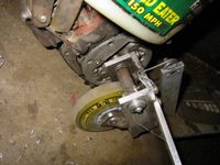 This is a better picture of the drive roller. Notice the cable attached to the pivoting bracket. Through a lever on the handle bar of the scooter (a brake lever from a bike), the cable pulls the bracket and roller off the wheel and acts as a clutch.
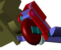 This is a CAD model of the power unit. Notice the light-green brake shoe to the bottom-right of the wheel. It is rigidly attached to the pivoting bracket (pivot point is the orange pin right above the brake shoe). When the clutch lever is pulled the drive roller is pulled away from the wheel, but the brake shoe moves toward the wheel because the brake shoe is mounted on the opposite side of the pivot point.The clutch lever, then, acts as a combination clutch/brake. It disengages the drive roller from the wheel when it is pulled half way; it engages the brake when it is pulled the whole length of its stroke. Genius!
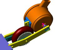 This is the electric version. You can see it’s a lot simpler in design.The round orange thing is the motor to which is attached a small sprocket. The yellow brackets mount the whole assembly on to the scooter. To the drive wheel I have attached a large sprocket, offset from the wheel with spacers to allow clearance for the chain. A loop of roller chain (not shown) transmits power from the motor to the wheel.
 This is a top view. Ya, I know the top yellow bracket is not attached to the scooter! So sue me!
Who doesn’t want to on their own business? Since I had the know-how and certain connections with local machine shops I thought I’d design and sell retrofit kits for Razor scooters. The first few picture below are of the first prototype I made using a small 18cc engine from a leaf blower. The pictures at the bottom are CAD models of the electric version I made. I actually made the electric version, but I don’t have any photographs to post.
After looking into liability issues I realized it as going to take a lot more money, time and research to make this venture work. I was due to start law school in a few months so I abandoned the idea. Now the market is flooded with powered scooters and prices have dropped dramatically. C’est la vie.
 Shown here leaning up against my milling machine on which I made all the parts for this scooter.In the background you can see some of the trimmers I was going to cannibalize for parts. I got a good deal on "remanufactured" trimmers from Harbor Freight, though it turns out all the engines were brand new.
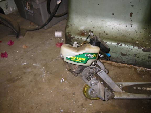 A better view of the power unit. The engine is mounted on a pivoting bracket. At the bottom you can see one of a pair of springs. The pivot point is that pin right above the spring. The springs keep the drive roller (pictured below) pressing on the drive wheel.
 This is a better picture of the drive roller. Notice the cable attached to the pivoting bracket. Through a lever on the handle bar of the scooter (a brake lever from a bike), the cable pulls the bracket and roller off the wheel and acts as a clutch.
 This is a CAD model of the power unit. Notice the light-green brake shoe to the bottom-right of the wheel. It is rigidly attached to the pivoting bracket (pivot point is the orange pin right above the brake shoe). When the clutch lever is pulled the drive roller is pulled away from the wheel, but the brake shoe moves toward the wheel because the brake shoe is mounted on the opposite side of the pivot point.The clutch lever, then, acts as a combination clutch/brake. It disengages the drive roller from the wheel when it is pulled half way; it engages the brake when it is pulled the whole length of its stroke. Genius!
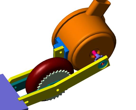 This is the electric version. You can see it’s a lot simpler in design.The round orange thing is the motor to which is attached a small sprocket. The yellow brackets mount the whole assembly on to the scooter. To the drive wheel I have attached a large sprocket, offset from the wheel with spacers to allow clearance for the chain. A loop of roller chain (not shown) transmits power from the motor to the wheel.
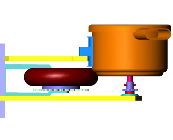 This is a top view. Ya, I know the top yellow bracket is not attached to the scooter! So sue me!
posted by anchovy @ 9:25 AM
![]()


2 Comments:
At 10:47 AM, mal said…
Way cool! probably just as well you did not go in the biz, it probably would have created a shortage of weed eaters. I am not sure our economy could stand that *G*
At 7:53 PM, anchovy said…
Gee thanks. I thought it was pretty cool too. Turns out the polyurethane wheels were too brittle and the shock transmitted by the sudden engagement of the drive roller tended to chip away chunks of the wheel. Besides, the drive roller itself would wear away. If you check out the commercial scooters, their own drive rollers have gone through a materials evolution culminating in ceramic rollers (super hard and wear resistant).
There's a funny story associated with the electric scooter I think I may write about in a subsequent post.
Post a Comment
<< Home